Shandong Fengtu IOT Technology Co., Ltd
Sales Manager:Ms. Emily Wang
Cel,Whatsapp,Wechat:+86 15898932201
Email:info@fengtutec.com
Add:No. 155 Optoelectronic Industry Accelerator, Gaoxin District, Weifang, Shandong, China


Sales Manager:Ms. Emily Wang
Cel,Whatsapp,Wechat:+86 15898932201
Email:info@fengtutec.com
Add:No. 155 Optoelectronic Industry Accelerator, Gaoxin District, Weifang, Shandong, China
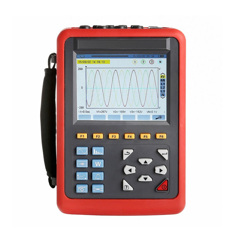
Model:FT-DN5000
Brand:fengtu
Electrical Power Analyzer is a portable field power measurement instrument for power consumption measurement and power quality analysis of power supply lines.
Electrical Power Analyzer Product Features
1. Provides comprehensive analysis and diagnostics for all electrical parameters, including voltage, current, power, energy, harmonics, and phase.
2. Offers a variety of current sensors to suit diverse application environments.
3. Features 4-channel current and 4-channel voltage measurement, simultaneously capturing and recording electrical parameters and waveforms to provide all the power quality information you need for your work.
4. Recorded data can be exported to generate analysis reports in compliance with national standards.
Electrical Power Analyzer Product Functions
1. Testing Functions: Real-time waveform display (4 voltage channels/4 current channels); true RMS values for voltage and current; DC component of voltage; peak values for voltage and current; maximum/minimum values of voltage and current over a specified period; phasor diagram display; harmonic measurement for each phase (up to the 50th harmonic); bar chart display of harmonic ratios for voltage and current; calculation of Total Harmonic Distortion (THD); active, reactive, and apparent power (per phase and total); active, reactive, and apparent energy (per phase and total); transformer K-factor calculation; displacement power factor (DPF) and power factor (PF) calculation; flicker calculation; and three-phase unbalance calculation (for both voltage and current).
2. Capture and Monitoring Functions: Capable of detecting and capturing transient changes in power grid voltage and current parameters, including fluctuations, swells, dips, short-duration interruptions, transient overvoltages, inrush currents, and instantaneous waveform distortions. The instrument can store up to 150 sets of transient waveforms.
3. Inrush Current Monitoring: Capable of monitoring line surge currents and the inrush currents of electrical equipment during startup—a feature that assists in the accurate design of installed capacity. It can display the rise/fall curves of RMS values during startup, the envelope curve of the inrush current, and the waveforms for all 4 voltage and 4 current channels. Upon triggering, the device can record for approximately 100 seconds, capturing the instantaneous values and waveforms for every cycle within that duration. 4. Data Recording and Storage: The device can record all test parameters associated with its basic testing functions—including Urms, Uthd, Ucf, Uunb, Hz, Vrms, Vthd, Vcf, Vunb, PST, Arms, Athd, Acf, Aunb, KF, W, VAR, VA, PF, COSφ, and TANφ—as well as the 50th-order harmonics for both voltage and current (totaling 123 parameters). It generates trend curves and supports long-term data recording. (For example, recording 20 selected parameters at 1-minute intervals allows for approximately 300 days of continuous data logging.)
5. Alarm Function: Users can set specific limits for selected parameters to monitor for threshold violations. When a limit is exceeded—such as in cases of overvoltage, overcurrent, excessive unbalance, harmonic distortion (individual or total), frequency deviation, or active power limits—an alarm log is generated. Up to 40 sets of alarm monitoring parameters can be configured; each set can include different parameters (from the 123 available, including 50th-order harmonics) and specific threshold limits, along with a defined minimum duration for a violation to trigger an alarm. The device can store up to 12,800 alarm log entries.
6. Screenshot Function: Users can capture and save the current screen from any test page. Each screenshot is automatically saved with a timestamp and the corresponding test mode. Examples include captures of voltage/current waveforms, harmonic bar charts, and phasor diagrams. Up to 60 screenshots can be stored.
7. Communication Function: The device communicates with a PC via USB. Monitoring software allows for the real-time display of power quality waveforms and enables the retrieval of captured transient waveforms, trend records, alarm lists, and saved screenshots.
8. Settings: Users can configure the date and time, adjust display contrast and brightness, and assign specific colors to each phase line. The device allows for the configuration of wiring methods and power grid types. Users can also select different current clamps, define voltage transformation ratios, and toggle between Chinese and English menu interfaces. 9. Chinese/English Help Menu: At any stage of operation, you can press the "Help" key to access relevant help information.
Electrical Power Analyzer General Specifications
| Power supply | DC 7.4V, 5200mAh rechargeable lithium battery, external charger; operating current of approximately 490mA, battery continuous operation of about 8 hours. | ||
| Display | LCD color screen, 640 dots × 480 dots, 5.6 inches, display area 116mm × 88mm | ||
| Backlight function | Yes, suitable for dimly lit places and night use. | ||
| Current testing | Current Sensor: 008B; 040B; 068B; 300FA (Optional) | ||
| Voltage Test | Line voltage: 1.0V~2000V; Phase voltage: 1.0V~1000V | ||
| Power and energy parameters | W, VA, var, PF, DPF, cosφ, tanφ; Wh, Varh, Vah | ||
| Number of channels | 4-wire voltage, 4-wire current | ||
| Three-phase unbalance | Yes | Inrush current mode | Yes, 100 seconds |
| Frequency | 40Hz~70Hz | Peak | Yes |
| Harmonics | Yes, 0-50 times | Display of the phase diagram | Automatic |
| Total Harmonic Distortion | Yes, 0-50 times, each phase | Screenshot capacity | 60 |
| Number of transient records | 150 sets | Menu language | Chinese, English |
| Voltage Flicker | Yes | Communication Interface | USB |
| Record | 300 days (recording 20 parameters simultaneously, 1 point every 1 minute) | ||
| Minimum/Maximum Record Value | Yes, the maximum and minimum values over a period of time can be measured. | ||
| Alert | 40 different types of parameter selection, 12,800 sets of alarm logs | ||
| Automatic shutdown | Under the alarm/trend recording/transient capture mode (waiting or in progress), the instrument will not shut down automatically. | ||
| In other test modes, if there is no key operation within 15 minutes, it will prompt for automatic shutdown after 1 minute. | |||
| Battery charge indicator | The battery icon shows the charge level, and when the battery is too low, it will prompt for an automatic shutdown in 1 minute. | ||
| Input impedance | The test voltage input impedance is: 1MΩ | ||
| Instrument dimensions | 240mm×170mm×68mm | ||
| Instrument Quality | Approx. 8.4 kg (including packaging and full set of current clamps) | ||
| Suitable for safety regulations | IEC 61010 1000V CAT III / 600V CAT IV, IEC61010-031, IEC61326, Pollution Degree 2 | ||
| Random attachment | Host: 1 unit; Tool kit: 1 unit; Test probes: 5 (1 yellow, 1 green, 1 red, 1 black, 1 blue); Alligator clips: 5 units; Charger: 1 unit; 8G memory card: 1 unit; Current sensor: Optional | ||
Electrical Power Analyzer Current Sensor Characteristics (Optional Accessory)
| Current sensor model | Current clamp | Current True RMS | Current True RMS Maximum Error | Phase angle φ Maximum error |
| 008BCT size: Φ8mm | 10mA to 99mA | ±(1%rdg+3dgt) | ±(1.5°), Arms≥20mA | |
| 100mA to 10.0A | ±(1%rdg+3dgt) | ±(1°) | ||
| 040BCT size: Φ40mm | 0.10A~0.99A | ±(1%rdg+3dgt) | ±(1.5°) | |
| 1.00A to 100A | ±(1%rdg+3dgt) | ±(1°) | ||
| 068BCT size: Φ68mm | 1.0A to 9.9A | ±(2%rdg+3dgt) | ±(3°) | |
| 10.0A to 1000A | ±(2%rdg+3dgt) | ±(2°) | ||
| 300FACT Size: Φ300mm | 10A~99A | ±(1%rdg+3dgt) | ±(3°) | |
| 100A~6000A | ±(1%rdg+3dgt) | ±(2°) |
Electrical Power Analyzer Instrument accuracy
| Measurement Specifications | Measurement Range | Display resolution | Maximum error within the reference range |
| Frequency | 40Hz~70Hz | 0.01Hz | ±(0.03)Hz |
| Phase voltage true RMS | 1.0V to 1000V | Minimum resolution 0.1V | ±(0.5%rdg+5dgt) |
| Line voltage true RMS | 1.0V to 2000V | Minimum resolution 0.1V | ±(0.5%rdg+5dgt) |
| DC voltage | 1.0V to 1000V | Minimum resolution 0.1V | ±(1.0%rdg+5dgt) |
| Current True RMS | 10mA to 6000A | Minimum resolution 1mA | ±(0.5%rdg+2dgt) |
| Phase voltage peak | 1.0V to 1414V | Minimum resolution 0.1V | ±(1.0%rdg+5dgt) |
| Line voltage peak | 1.0V to 2828V | Minimum resolution 0.1V | ±(1.0%rdg+5dgt) |
| Current Peak | 10mA to 6000A | Minimum resolution 1mA | ±(1.0%rdg+5dgt) |
| Peak factor | 1.00~3.99 | 0.01 | ±(1%rdg+2dgt) |
| 4.00~9.99 | 0.01 | ±(5%rdg+2dgt) | |
| Active power | 0.000W~9999.9kW | Minimum resolution 0.001W | ±(1%rdg+3dgt); Cosφ≥0.8 |
| ±(1.5%rdg+10dgt); 0.2≤Cosφ<0.8 | |||
| Reactive power inductive & capacitive | 0.000VAR~9999.9kVAR | Minimum resolution 0.001VAR | ±(1%rdg+3dgt); Sinφ≥0.5 |
| ±(1.5%rdg+10dgt); 0.2≤Sinφ<0.5 | |||
| Apparent power | 0.000VA~9999.9kVA | Minimum resolution 0.001VA | ±(1%rdg+3dgt) |
| Power factor | -1.000 to 1.000 | 0.001 | ±(1.5%rdg+3dgt); Cosφ≥0.5 |
| ±(1.5%rdg+10dgt); 0.2≤Cosφ<0.5 | |||
| Active power | 0.000Wh~9999.9MWh | Minimum resolution 0.001Wh | ±(1%rdg+3dgt); Cosφ≥0.8 |
| ±(1.5%rdg+10dgt); 0.2≤Cosφ<0.8 | |||
| Reactive power: inductive & capacitive | 0.000 VARh ~ 9999.9 MVARh | Minimum resolution 0.001VARh | ±(1%rdg+3dgt); Sinφ≥0.5 |
| ±(1.5%rdg+10dgt); 0.2≤Sinφ<0.5 | |||
| Visible electricity | 0.000VAh~9999.9MVAh | Minimum resolution 0.001VAh | ±(1%rdg+3dgt) |
| Phase angle | -179° to 180° | 1° | ±(2°) |
| Tanφ(VA≥50VA) | -32.768~32.768 | Minimum resolution 0.001 | ±(1%rdg+5dgt) |
| Displacement Power Factor (DPF) | -1.000 to 1.000 | 0.001 | ±(1%rdg+5dgt) |
| Harmonic ratio (Vrms > 50V) | 0.0%~99.9% | 0.1% | ±(1%rdg+5dgt) |
| Harmonic angle (Vrms > 50V) | -179° to 180° | 1° | ±(3°) harmonics 1-25 times |
| ± (10°) harmonics 26 to 50 | |||
| Total Harmonic Distortion (DF or THD-F) ≤ 50 | 0.0%~99.9% | 0.1% | ±(1%rdg+5dgt) |
| Distortion factor (DF or THD-R) ≤ 50 | 0.0%~99.9% | 0.1% | ±(1%rdg+10dgt) |
| Transformer K-factor | 1.00~99.99 | 0.01 | ±(5%) |
| Three-phase imbalance | 0.0%~100% | 0.1% | ±(1%) |
Water and Rain Monitoring SystemWater and rain conditions are important hydrological reference materials and are of great significance in regional water resources allocation and management. It refers to the water and rain conditions, and the specific index parameters are water level, flow rate, flow...
Small weather monitoring station, is an automated instrument in weather data collection, analysis and processing. It collects and stores and organizes physical quantities such as temperature and humidity in the atmosphere and then converts them into displayable graphics or text for managers to use....
iot sensors are hardware components that detect changes in the environment and collect data for collecting data from the surrounding environment and transmitting it over the network....
wind speed sensors are ultrasonic sensors that measure wind speed and direction, providing important data for meteorological research, aviation, offshore operations, and more....


 Get a Free Quote
 Skype
 whatsapp
 mail